

1500W Electric MTB Bicycle Build (65 Km/h) : 6 Steps (with Pictures) - chanplacre1939
Introduction: 1500W Physical phenomenon MTB Wheel Construct (65 Kph)
Hi! Thanks for checking out one more project of mine. Hope you will like this unrivalled as overmuch as I did.
I've been planning this propose for quite an some time and now that I have information technology finally finished I am stoked to be competent to share the inside information of how I built it and how it performs.
Earlier we dive in to the details, make sure you watch my picture supra where I show the complete process of the electric pedal (e-bike) build up, which includes upgrading my DIY spot-welder, edifice the battery and installment the e-bike kit components.
As always I make sure to place active golf links for parts and tools for making this awesome externalise clean which you testament find in the next step.
I also want to point out that you should feel free to ask me whatever questions regarding the build, I will be to a higher degree happy to help anytime.
Let's plunk in to the build!
Step 1: Design, Parts and Tools
- To build win over your bicycle to a brawny e-bike like this one, you'll in spades need to get the 1500W physical phenomenon bicycle conversion kit. More along information technology later. The kit uses a 7-speed cassette, so if you are running 9 gears along your bicycle OR more, you will pauperism to 'downgrade' to a 7-hurry system. For that you'll need a rear derailleur and a matching shifter. The front derailleur won't be needed if you are planning to more often than not utilize it on matted roads, though it handles slopes with ease.
While trying to figure out the proper design for this e-cycle conversion envision, the main struggle I faced was sourcing a size of it Significant full suspension system mountain bike. Of course I was looking at for a second-hand one to maintain the low budget of the build up, even keeping the completed e-bike cosy and nice to ride. Finding a decent second-manus glutted abatement bicycle really took me the longest - almost uncomplete a twelvemonth. Therein time I could only witness a handful of offers where I exist.
I was lucky enough to purchase this quite a immemorial Dice AMS Favoring CC with 26" wheels which was in great shape, really. It was ridden mostly by the beach area, so lots of Amandine Aurore Lucie Dupin had to be cleaned disconnected beforehand. What I also loved about this bike is that IT has a spate of space in the skeletal frame to accommodate the large stamp battery pack I built. Of course IT would have been a good deal simpler if I just secondhand a hardtail, but full dangling bikes (even old as this one) ride much softer, especially with a massive hub motor at the rear.
Probably the most pricey firearm of this build is the battery. Since IT is the power unit of the whole bike, information technology needs to output enough current for the coercive hub efferent in the tush. I definite to progress the battery myself and place it in a plastic case to represent able to remove the battery from the bike when needed. To my eye information technology looks more paid and neat when the barrage is mounted onto a frame in a plastic caseful. More on the battery material body in step 3.
To build my own battery I required to upgrade my on-line spot welder for meliorate weld quality. Deep instructions on building (upgrading) one in step 2.
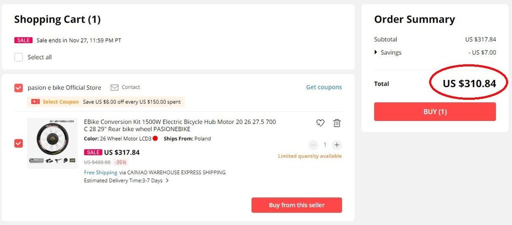
Below I have placed the links for every part (pretty much) that has been ill-used for the build. The independent star of the show being the 1500W E-bike conversion kit, which is one of the best purchases I have made in a monthlong time. I chose the 26" model but there are plenty of wheel around sizes for you to choose from. For directly, I could non source a best deal than this peerless. (Beneath is the price shown at the time of making this Instructable)
The kit up arrives with loads of parts, including the following:
- Powerful 1500W rear hub causative tied on to a heavy MTX39 rim
- 18 Mosfet wholesome wave controller
- LCD display
- Throttle with lock and key
- Brake levers with king decreased-off switches
- Pedal point assist sensor
- Maxxis tyre
- 160 millimetre brake platter rotor
- Technology grips
- Controller mounts, cables, zip ties, etc.
$18 Sour your first App order 🎁 https://a.aliexpress.com/_mNHt1sn
Parts for E-wheel:
- 1500W E-Bike kit up 🛒👉🏻 https://bit.ly/38WHV0J
- Different kits 👇🏻
-
► https://bit.ly/3eR97iW
-
► https://number.ly/3e0CbWx
-
► https://bit.ly/3lzAzqE
-
► https://amzn.to/3qcVwpK
-
► https://ebay.America/T8fQ8m
- Concentrated battery carry (52V):
► https://bit.ly/3nFormU
► https://second.ly/3vwGT3I
► https://bit.ly/2RhPCIg
► https://bite.ly/37lGFSZ
- Charger with XLR plug - https://second.ly/2J2FmA4
- M6 rivnuts - https://bit.ly/3maHzHQ
- M6 bolts (30mm) - https://flake.ly/369D4rC
- Waterproof case (158x90x60) - https://bit.ly/377ZQiQ
- Torque fortify - https://bit.ly/3q37uUb
- Crankset - https://bit.ly/3o0n29i
- Chainring - https://bit.ly/3ec6jhe
- Hydraulic brakes - https://bit.ly/3rZqK6j
- Bracken calipers - https://bit.ly/33mlZsu
- 7 speed chain of mountains - https://bit.ly/3ygElYF
- 7 speed Chain link - https://bit.ly/3lwiJ7R
- Handlebar extension - https://bit.ly/37aleE7
- Telephone bearer - https://act.ly/3ioUVRi
- 7 speed rear derailleur - https://bit.ly/3pZha1U
- Gearshift (7 speed) - https://bit.ly/2QQ6aXZ
- Pedals - https://bit.ly/3nTJHFL
𝗣𝗮𝗿𝘁𝘀 𝗳𝗼𝗿 𝗯𝗮𝘁𝘁𝗲𝗿𝘆 𝗽𝗮𝗰𝗸:
Li-Ion batteries (84 pcs) :
► https://bit.ly/3kW4x45
► https://moment.ly/37jWPwj
► https://bit.ly/3xovROI
► https://bit.ly/2TWXbG7
- Smart BMS (14S 40A + BT faculty) - https://bit.ly/3rTvrPd
- Barrage case (52V) - https://moment.ly/37TsbLp
- Saturated Ni strip (0.15x8mmx5m) - https://ebay.United States of America/c4Rhds
- Kapton magnetic tape - https://moment.ly/2V330Pd
- Insulation rings - https://bit.ly/3nYW0PD
- Pasty foam - https://act.ly/3maMpF0
- Silicone wire (10AWG) - https://bit.ly/3yqyQrf
- XLR socket - https://bit.ly/33i0qsU
Click to see how to build this upgraded DIY spot-welder 👉🏻 https://youtu.be/y3zuP3vGXLk
Sequre SQ-SW1 Well-informed Spot Welder - https://chip.ly/3xbg06N (3% off with coupon code 𝗗𝗢𝗡𝗡𝗬𝗧𝗘𝗥𝗘𝗞)
𝗣𝗮𝗿𝘁𝘀 𝗳𝗼𝗿 𝘀𝗽𝗼𝘁 𝘄𝗲𝗹𝗱𝗲𝗿:
- Spot welder comptroller - https://bit.ly/3ybY8bV
- Welding handle - https://minute.ly/3dyk2y8
- 9V AC transformer - https://moment.ly/2To9TgA
- Nuke transformer - https://bit.ly/37kXqxF
- Cable connector (2 sets 35-50) - https://bit.ly/3waQttd
- Ft pedal switch - https://bit.ly/34R83Va
- 35mm² overseas telegram (3 meters) - https://bit.ly/2UVnJED
- Copper electrodes - https://bit.ly/35NRSti
- AC stimulus Jack - https://bit.ly/3y77DZU
- AC cord - https://bit.ly/36UkuRI
- 2.1mm DC input jack - https://bit.ly/35s1rxq
- Brass standoffs - https://bit.ly/2s4uFVb
- Heat quai tubing (12 mm) - https://chip.ly/35lWJmh
- Overseas telegram lugs 35-10 - https://bit.ly/3xfVeTu
- Enclosure - https://bit.ly/3qCZgD1 or https://moment.ly/3qCZgD1
𝗧𝗼𝗼𝗹𝘀:
- TS100 soldering iron - https://bit.ly/3kndDam
- Wide soldering tip (TS-C4) - https://flake.ly/36b67uT
- Cordless practice session - https://bit.ly/2UiMSbL
- Drill bit set - https://bit.ly/3kgSG0V
- Torsion wrench (1/4") - https://bit.ly/3fDm1ky
- Gist lick - https://bit.ly/2FWc3xu
- Wire ecdysiast - https://bit.ly/34kBgLn
- Step drill bits - https://act.ly/3eM5GtB
- Chain breaker - https://bit.ly/2V51EmZ
- Allen keys - https://bit.ly/3664O01
- Bottom bracket wrench - https://bit.ly/39gGU3R
Step 2: Building (upgrading) the Spot Welder
Making a spot welder yourself is actually a real easy farm out to do. But you take up to coif this at your own adventure. Basic knowledge of electronics and the dangers of it are most important.
List to the parts needed for the patch welder can be found above.
I have made a video on how I made-up my spot welder, merely I'm actually non too proud it. It definitely needs an upgrade - higher occurrent output for better welds and higher quality welding handles.
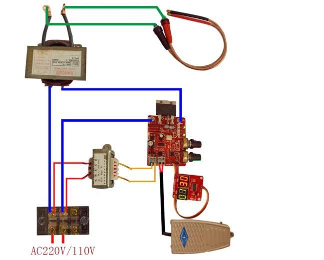
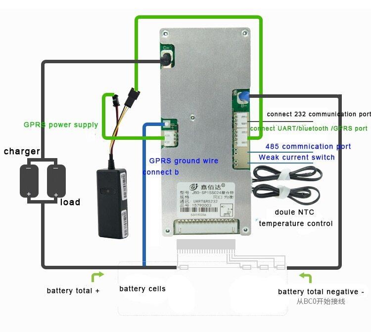
In that location is definitely many sources and tutorials online on how you can make a spot welder yourself for flash so I highly promote you to crack those knocked out for ideas. The design is real simple and all you au fon need is some thick cable, a transformer from a microwave and a controller, following with a couple of bits and pieces to nail the build. Refer to the wiring diagram shown below. Instead of the foot switch shown on the bottom right corner, we testament wire up a DC jack connector which will link up to the spy welding pen, which has a transposition mounted inside.
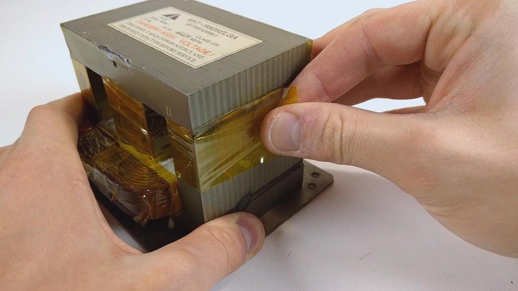
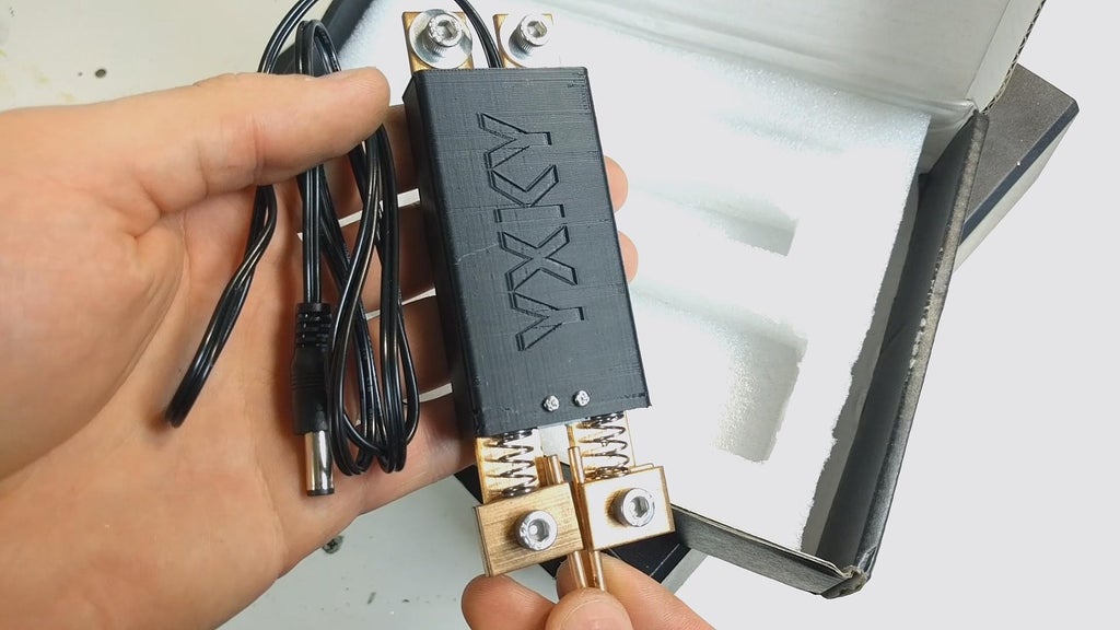
To upgrade my spot welder I got myself 2 meters of superiority 35 square millimeter copper cable and stripped off its insulation.
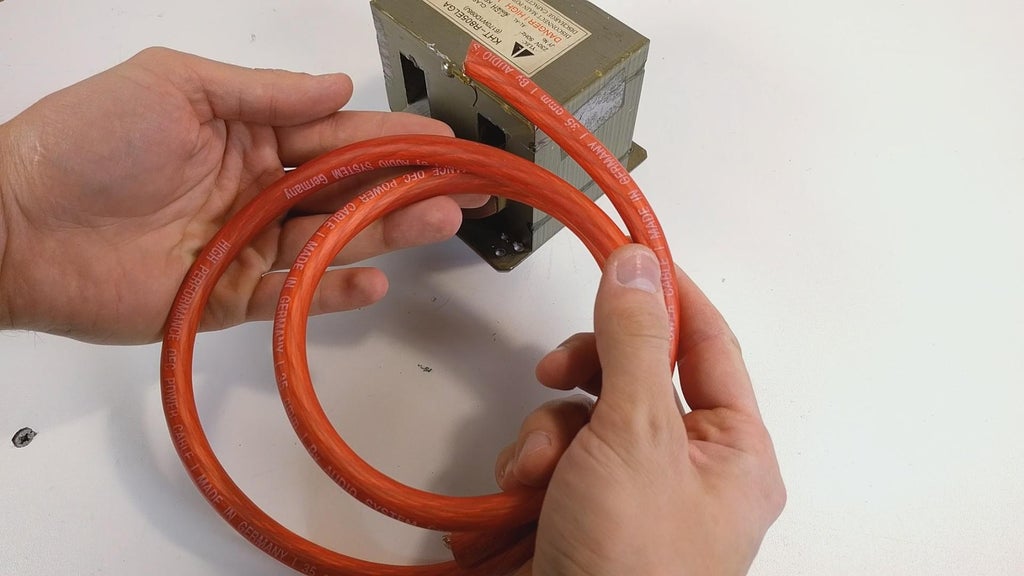

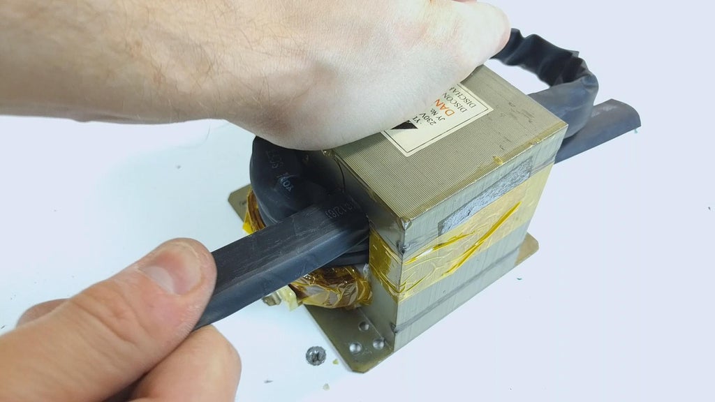
I then cut some heat shrink tubing the length of the telegraph and utilized it as a thin insulating material on the overseas telegram to pull round easier to wind it inside the transformer. Before winding the transformer with the newly insulated transmission line, I battlemented it with some Kapton tape. Getting 4 windings inside the transfomer is necessary but Crataegus laevigata be a bit tough to act. You can flatten the cable with a a few taps of a hammer beforehand to make information technology easier.
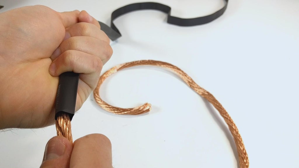
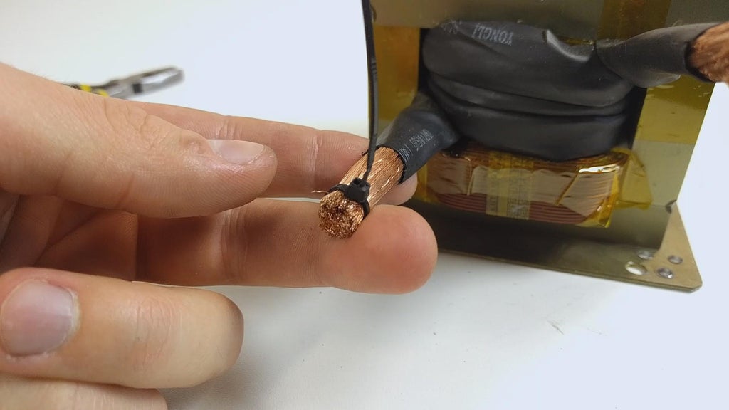
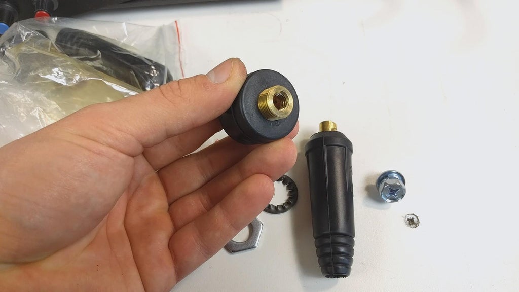
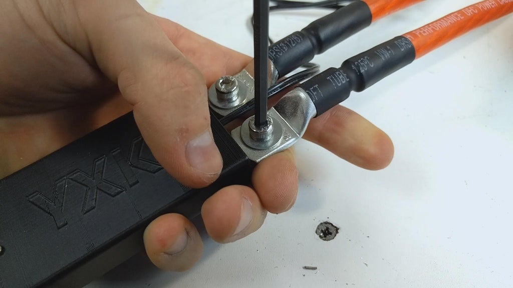
Now that I have got the telegraph dyspnoeal inside the transformer, I cut off a bit of the ignite shrink cancelled the ends of the cables and use zilch ties to compress the cable and arrive easier to slide a lug connector happening. I bent-grass the lug connectors at an angle for bolting it to the panel subsequent. Once they are fitted on, I applied extraordinary solder using a teensy torch flame.
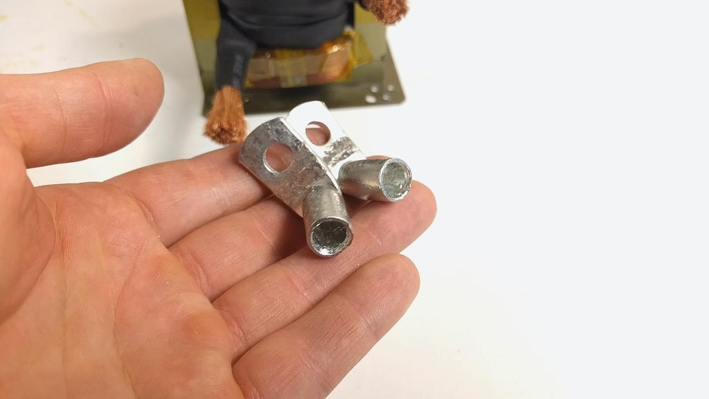

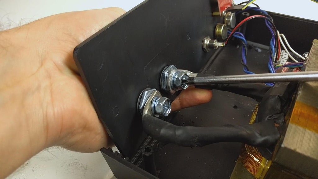
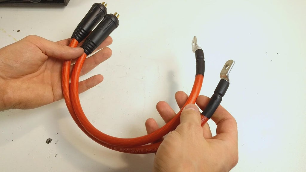
Now that I birth the lug nuts along the cable ends, I enlarged the previously ready-made holes in the front panel of the smudge welder with a step drill bit to a 14 mm hole. I then mounted the quick connectors to the panel and placed the transformer back in the box. One time the cable lugs are bolted to the quick connectors, I ready-made two cables for the welding pen to connect to. I commend you use at least a meter of cable for each. To those cables I connected the billet welding write using the provided bolts.
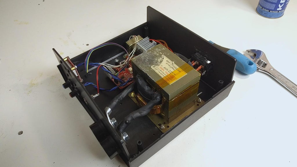
With that done, the place welder is completed (upgraded) and we force out move on to the battery build.
Step 3: Edifice the Battery

Disclosure: since there is more info online around building lithium-ion batteries than you could of all time read, I won't be going to the basics of construction batteries. If you doubt your knowledge all but building atomic number 3-ion battery packs, I highly suggest you get hold of a dependable read online or ticker plenty of videos on YouTube. The key here is construction a battery pack safely, because you should never underestimate the potential power of a lithium ion cell. Therefore you should know how to build a battery pack safely and hopefully you don't have to see yourself how IT erupts and catches on ardour (ask me how I lie with).
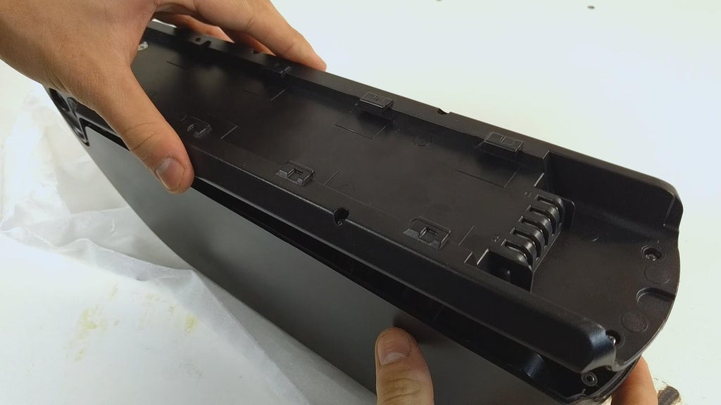
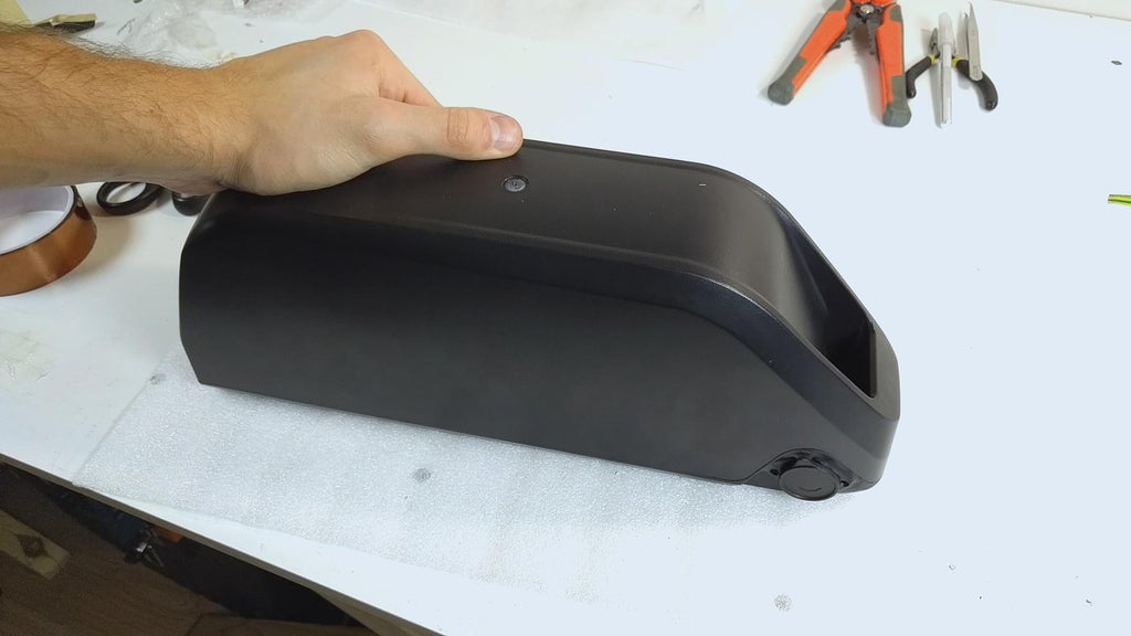
As I aforementioned before, my main neutral was to let a sleek looking ebike that would execute barely as comfortably. Therefore I chose to make a battery inside a case that I found online. My booming abeyance frame had plenty of space to fit the barrage thusly I went with a bad volumed character, that can actually fit 91 cells. The instance is actually of really nice prize, and can be mounted to the bike frame nicely and secure.
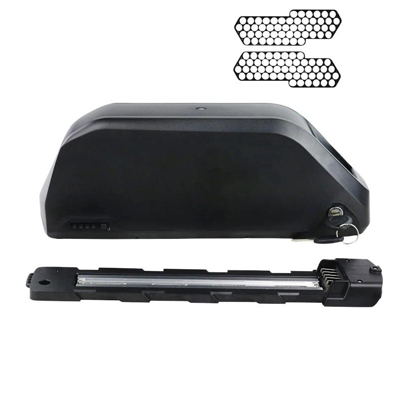
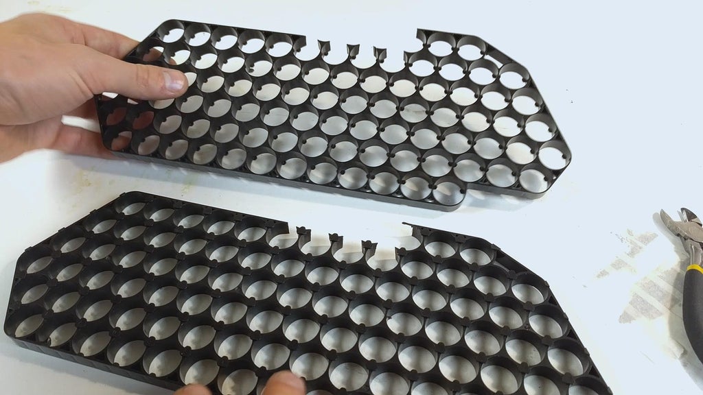
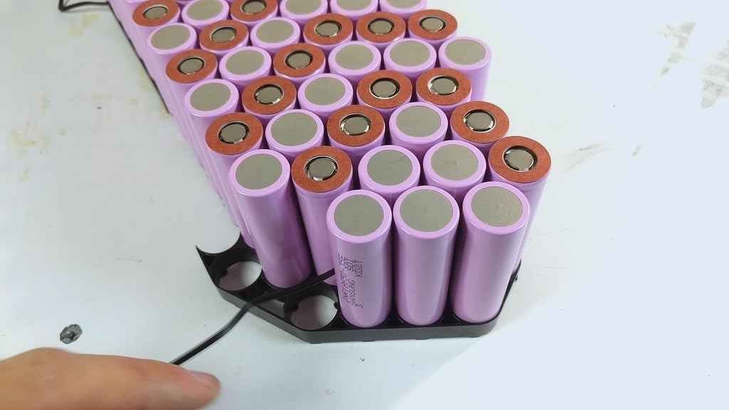
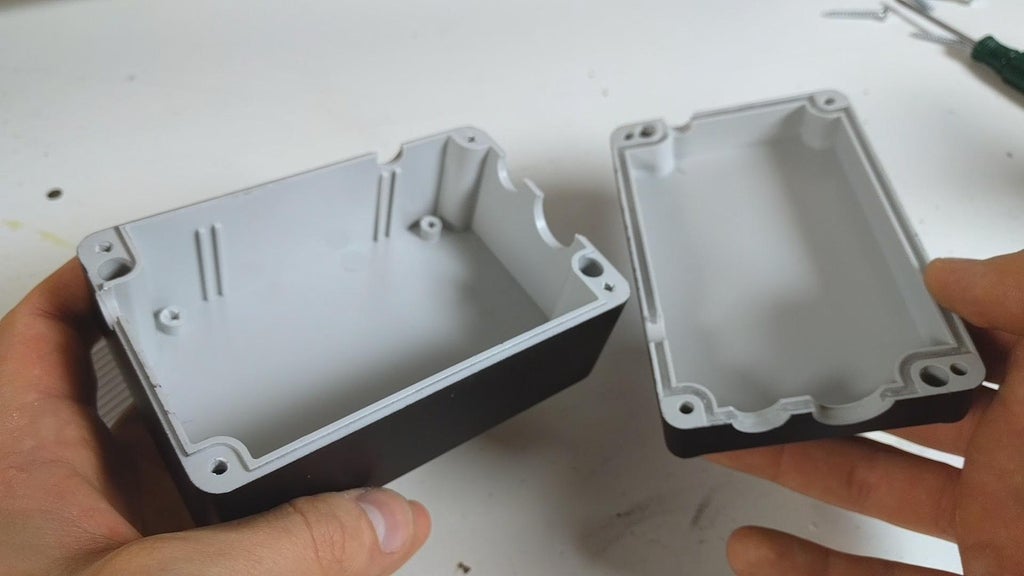
To start off, I remote the bottom of the battery encase and cut out a fewer pieces off the holders to make some place for the wise BMS circuit board we will be adding advanced. Since I am building a 52V 14S6P battery, I will have 7 unused holders consequently I can cut them disconnected.
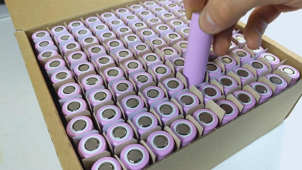
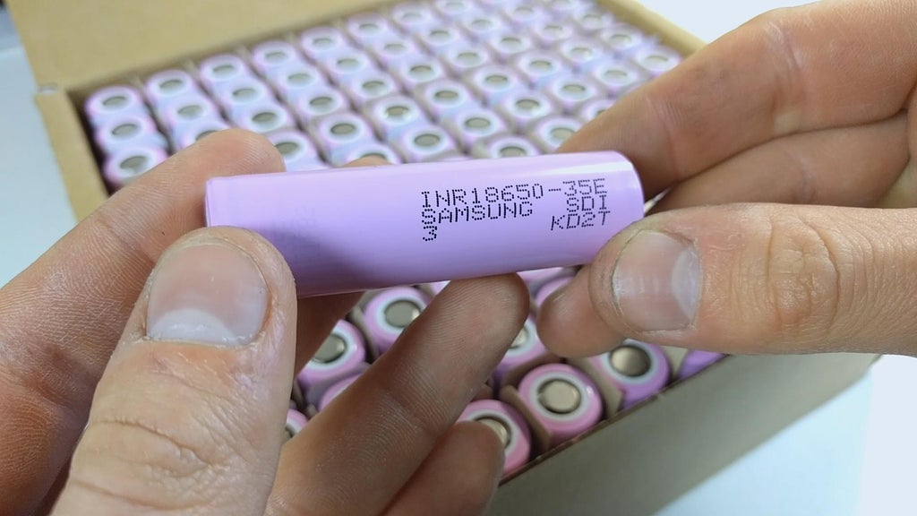
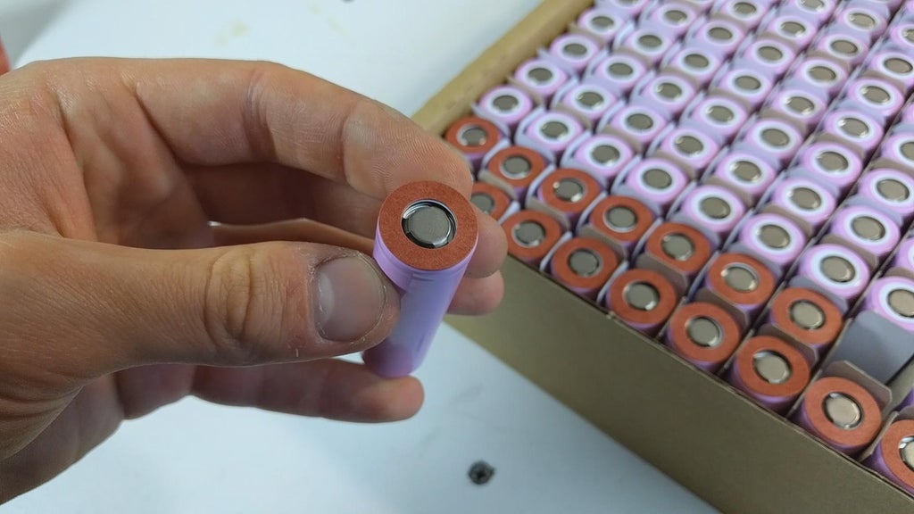
For the lithium-ion batteries I chose to accompany original Samsung INR18650-35E cells that I got from nkon.nl for a great damage. They take up a capacity of 3450mAh and a discharge current of 8A, which is perfect for powering the 1500W kit. I likewise found a sound informant of cells with in flood capacitance for cheap on Aliexpress, the link is in the opening move.
In front we kickoff assembling the battery pack, we need to protect the positive sides of the batteries of whatever short circuit theory. For that I will be using these sticky ring insulators.
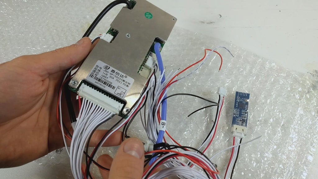
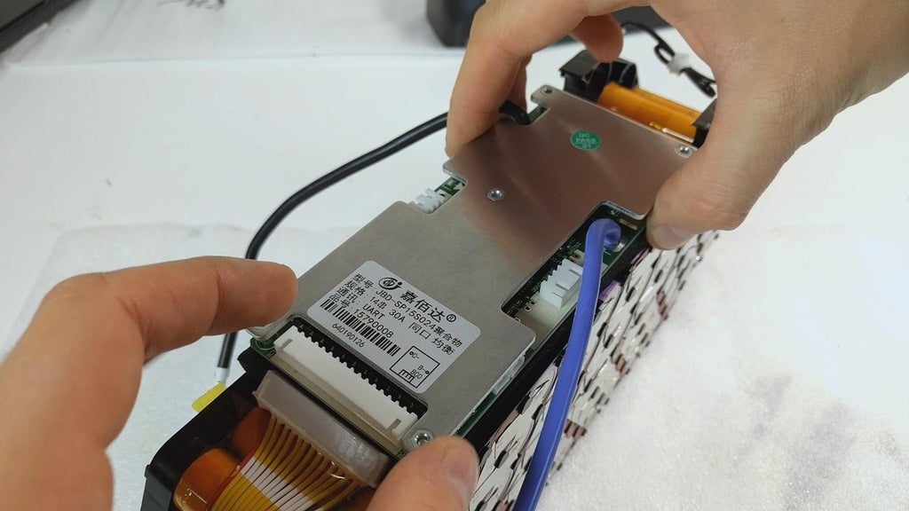
I highly recommend you use a smart BMS ilk the one I linked in the parts list. Make sure it comes with a Bluetooth adapter. This is a halting changer in monitoring your battery parameters including the power ouptut/input (when charging), correct temperature, speed, current and electric potential parameters.
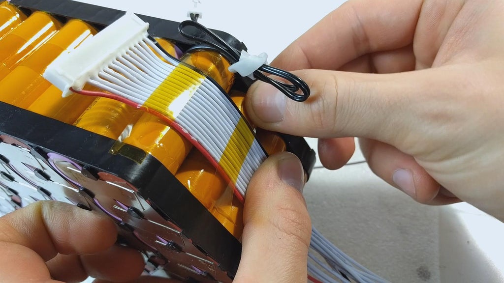
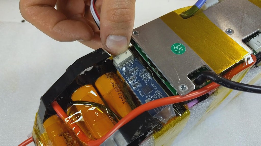
Before we take up assembling the battery pack, we need to disconnect the provided temperature sensors from the smart BMS get on. You may have single temperature sensor instead of two, depending along the model of your BMS.
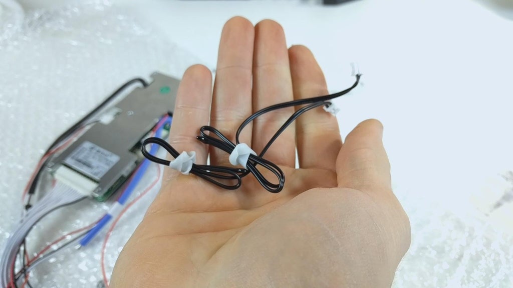
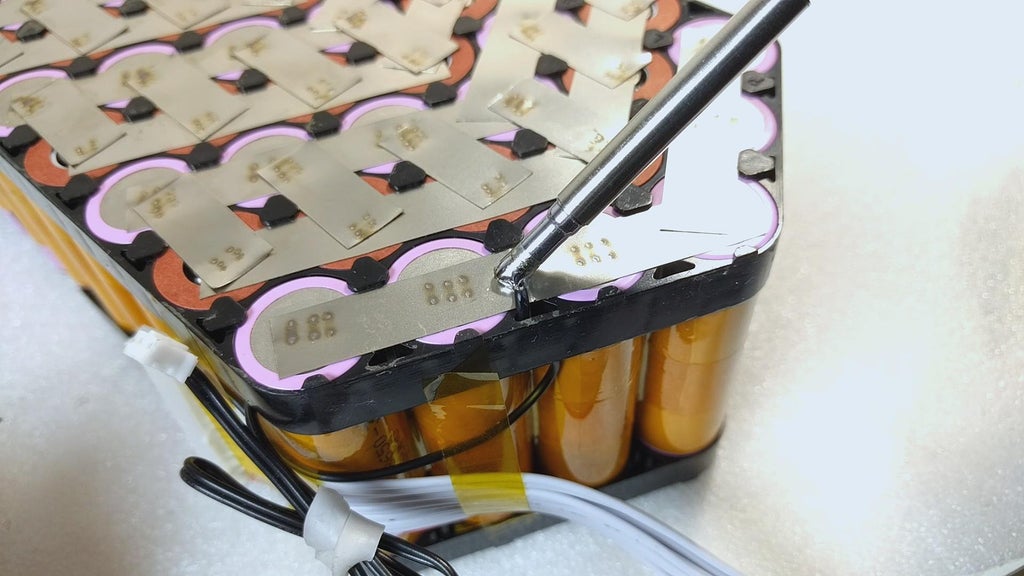
After placing the first 6 cells of the pack, using some Kapton tape and thermic paste, I attach unrivalled temperature sensor to one last of the battery bundle (negative side) and one sensor at the early broadside of the battery (positive side).
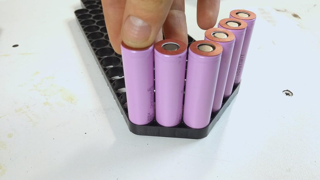
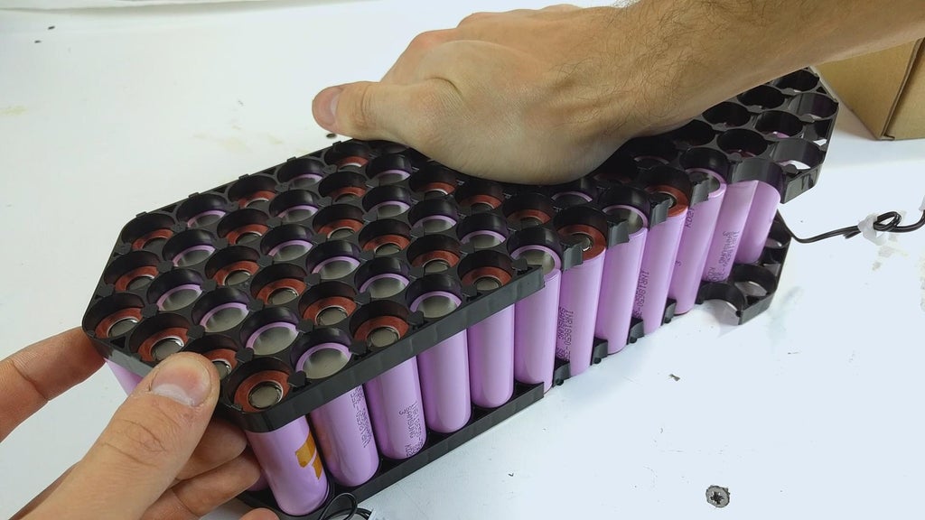
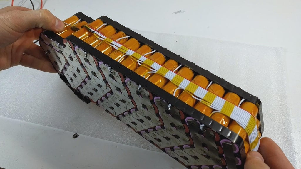
Once all the battery cells are in place, we can press down the other half of the frame. IT might take some pressure practical or a fewer light taps with a plastic mallet to sway the frame in place. Take your meter and make fated to align it properly so that no plastic wrap on the cells gets beaten-up.
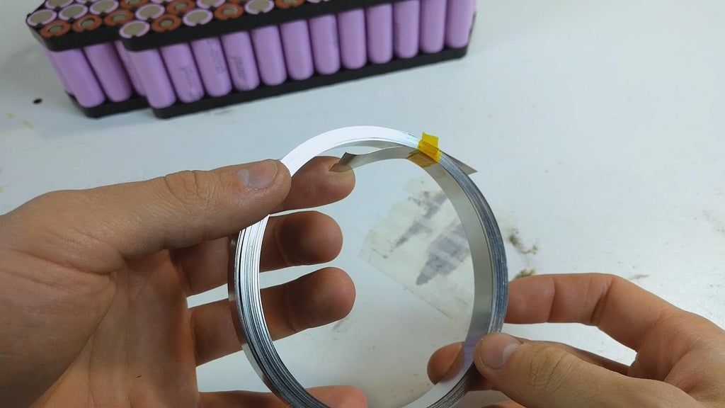
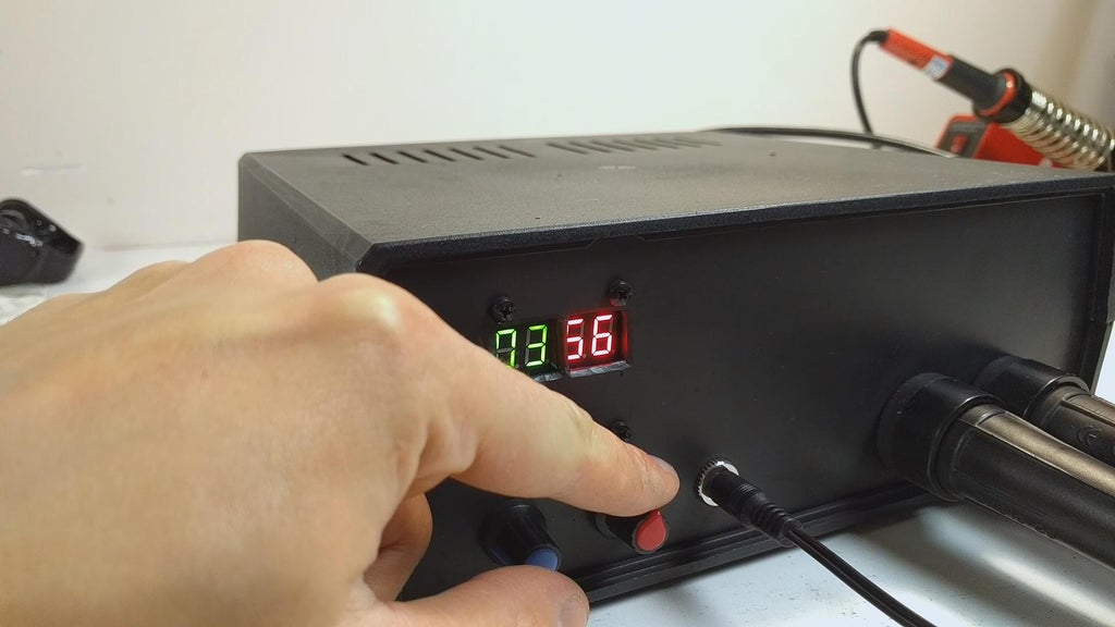
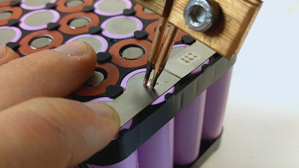
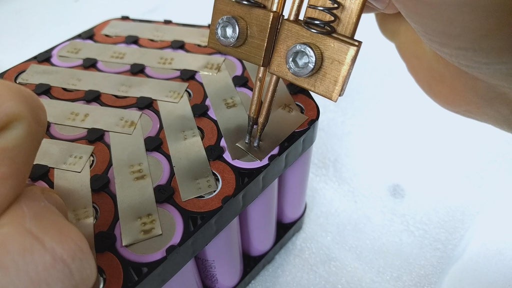
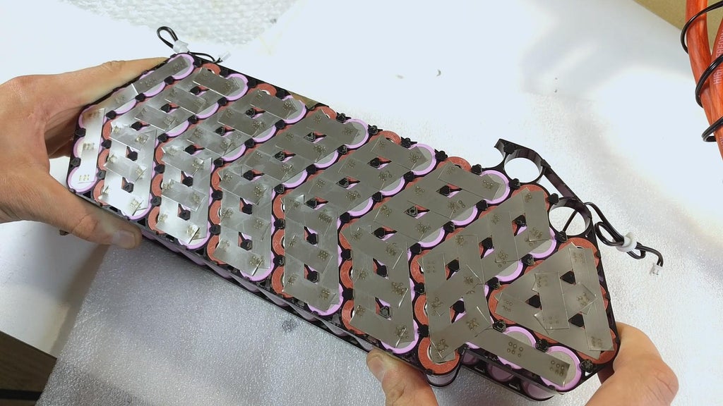
Now that the frame is in place, we can originate situatio welding the assault and battery cells by making the parallel connections across the battery ring. It is important to use high quality utter Ni strip. You can find the reservoir I put-upon in the parts heel above. Since my upgraded spot welder is capable of providing much more current, I proved the place welds on a battery shell that is completely looted. Afterwards lots of test welds I recovered away that the best welds are produced with the time set to 03 and the power to 56. If you succeed in getting 4 turns of 35mm² cable connected your transformer, your best settings should be more or less mine. Make sure to be welding roughly the centers of the battery cells.
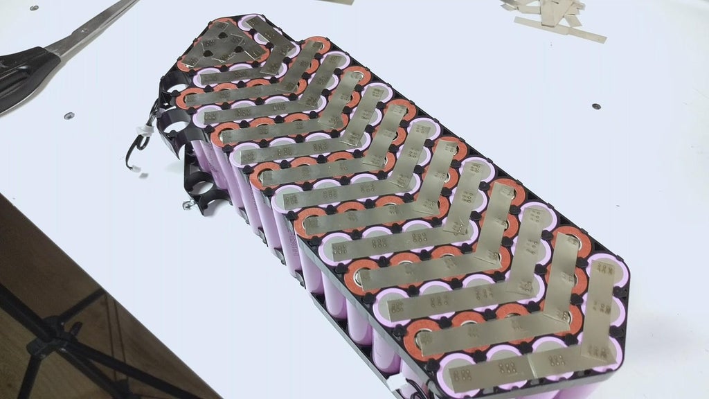
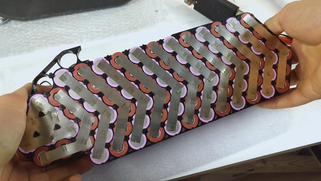
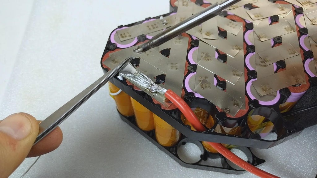
When the welds for nonconvergent connections are made, we can start welding the series connections. I cut a bunch of small nickel strips beforehand. I also layered the nickel strips at the points where the release wires will get soldered since most current will be flowing done those nickel strips.
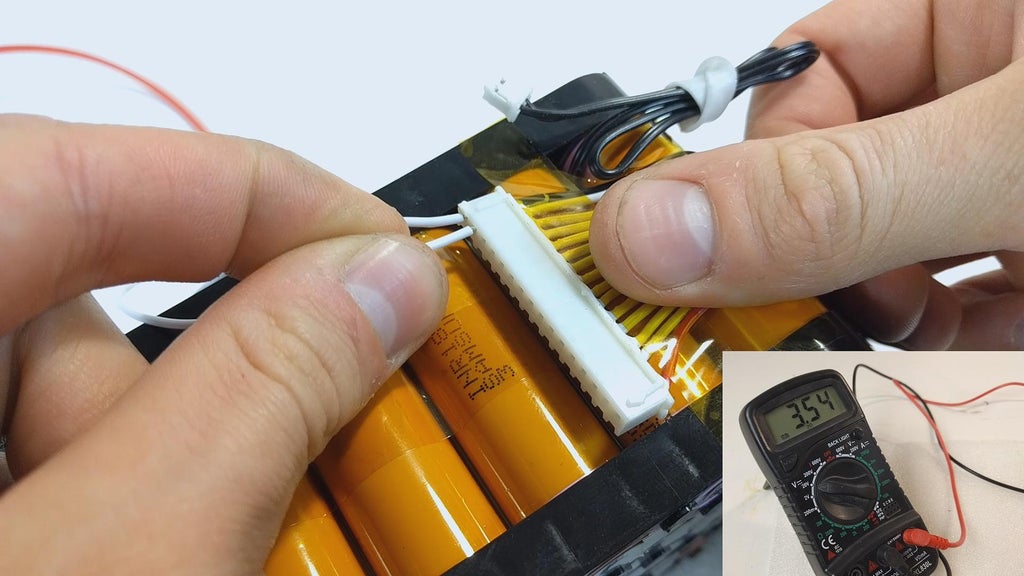
Once the serial publication connections are welded on, we can start soldering the balancing wires to the battery pack. Make sure IT is removed from the BMS to begin with. The unfavourable black wire of the balancing connector is soldered to the negative side of the battery and every other wire is soldered to the serial publication connection connected the battery pack, with the last-place red telegraph existence soldered to the positive side of the shelling. Click the link to download the Xiaoxiang BMS app. Touch to the diagram shown below for wiring the BMS board (GPRS faculty is optional):
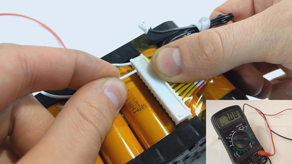
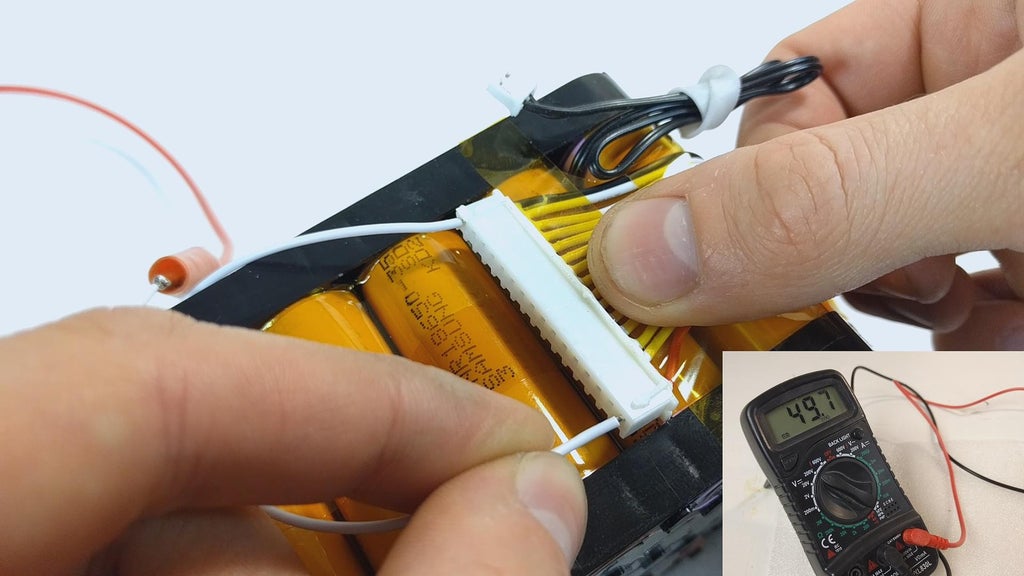
After soldering every balance telegraph to the serial publication connections, we need to make a point it is wired correctly. For that I inserted a thin telegraph into the black pin of the connector to connect IT to the negative lead of my voltmeter and other thin wire connected to the pin next to the ignominious one to connect information technology to the positive lead of the voltmeter. The voltage should read 3.6-4.2V depending on the state of charge of the cells. Moving the positive cozen to the adjacent stick it should read 7.2-8.4V and then on, until 50.4-58.8V are shown. If your measurings are inconsistent, you are likely to have soldered the balance leads incorrectly.
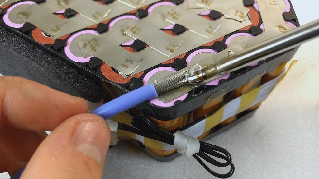
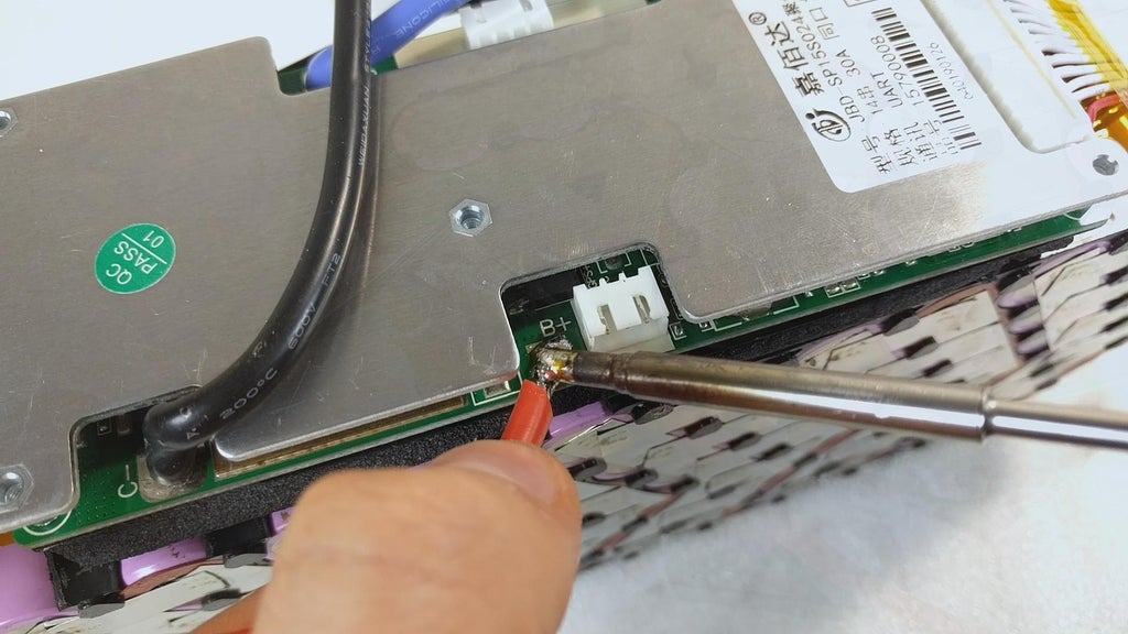
After ensuring the balancing wires are soldered correctly, we bathroom place the BMS happening some foam padding and solder the blue B- cable to the electronegative side of the battery. Once that is done the balancing connector can equal plugged in. We can now solder a length of 12AWG atomic number 14 wire from the formal side of the battery to the B+ link on the BMS. I have also added a short put together of same cable as a discharge wire.
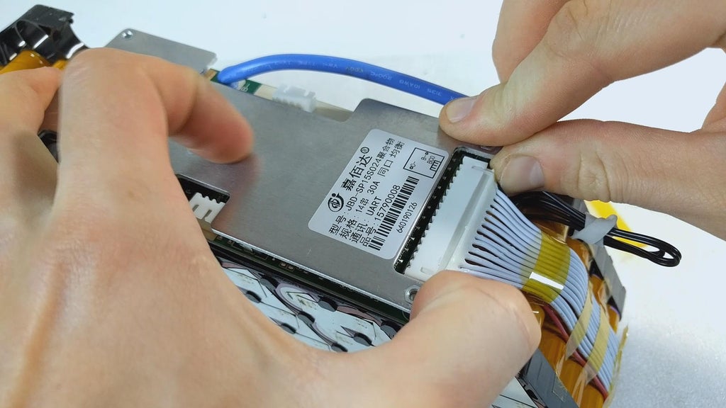
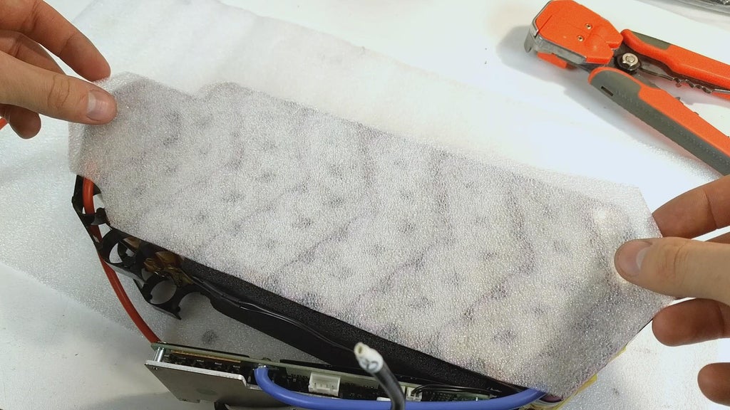
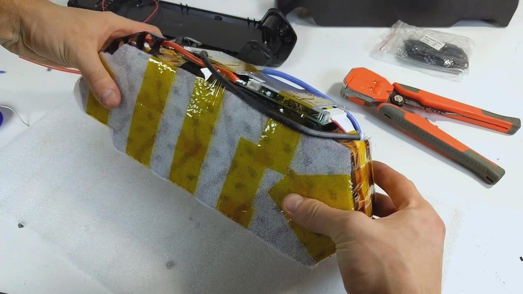
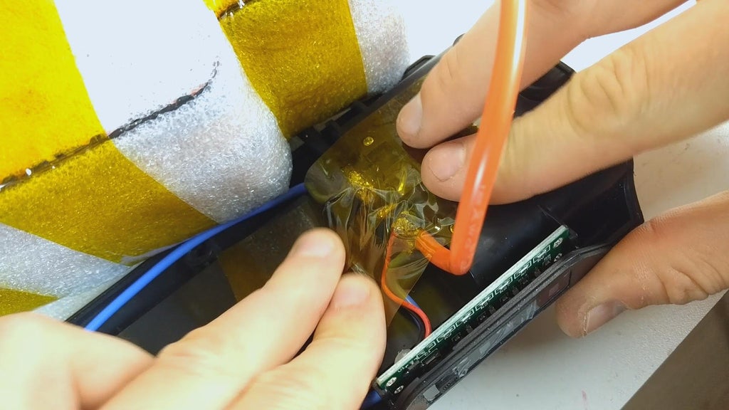
With the soldering completed happening the electric battery pack, we can insulate it with some foam and Kapton tape. With the battery safely insulated, I connected the temperature sensors back to the BMS and attached the Bluetooth vector exploitation a piece of double sided tape.
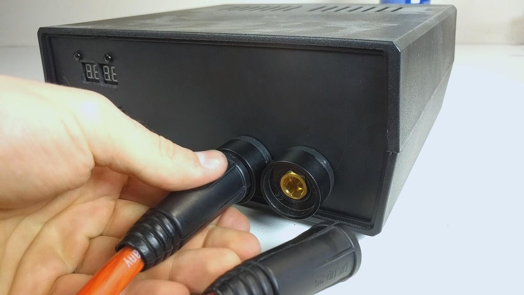
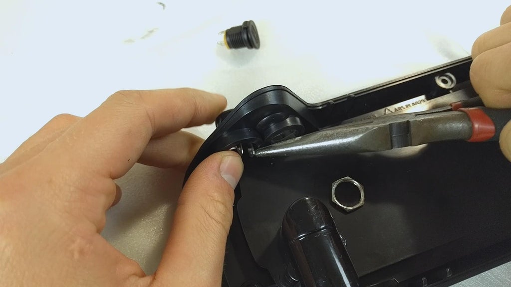
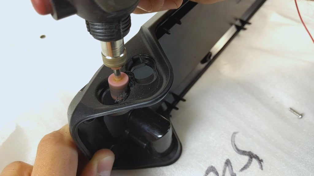
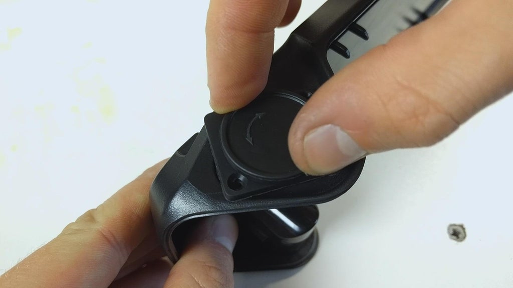
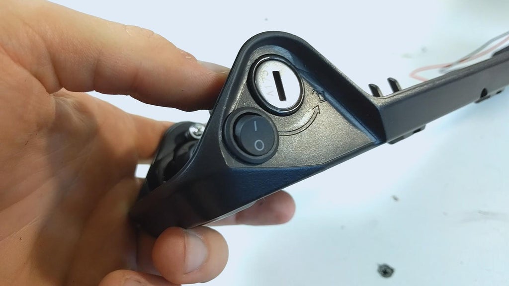
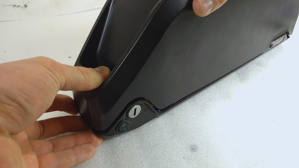
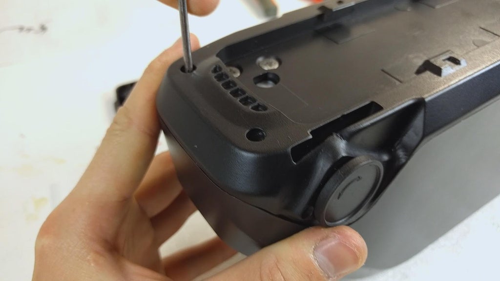
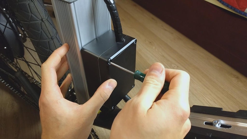
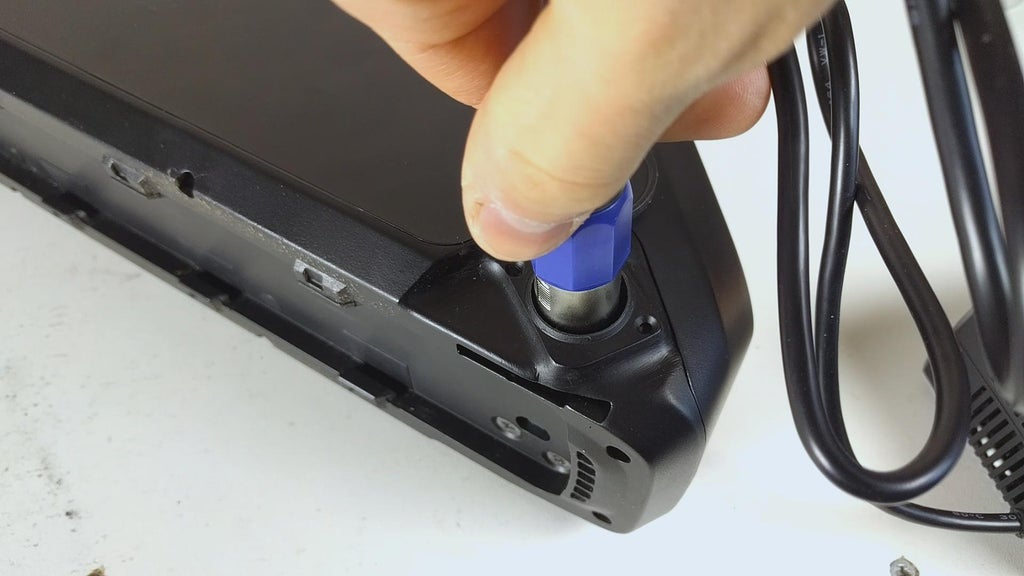
At the metre of filming this project, I was not able-bodied to source a large stamp battery case with a proper XLR connector for charging, so I had to make believe few tweaks to the enclosure myself. I started by removing the baron switch and the small jack that is supposed to be used for charging. Victimisation a dremel attachment I engraved out some impressible to place the XLR connector. Exploitation some epoxy resin for plastics I glued the port in situ and once it baked, I sanded the edges and sprayed some paint to go far look manufactory (kind of). I also relocated the power electric switch next to the lock but ended up not using it since I did non realise at first that the battery can Be turned off via Bluetooth on your phone.
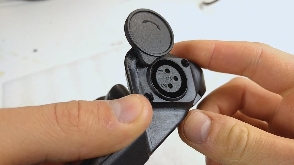
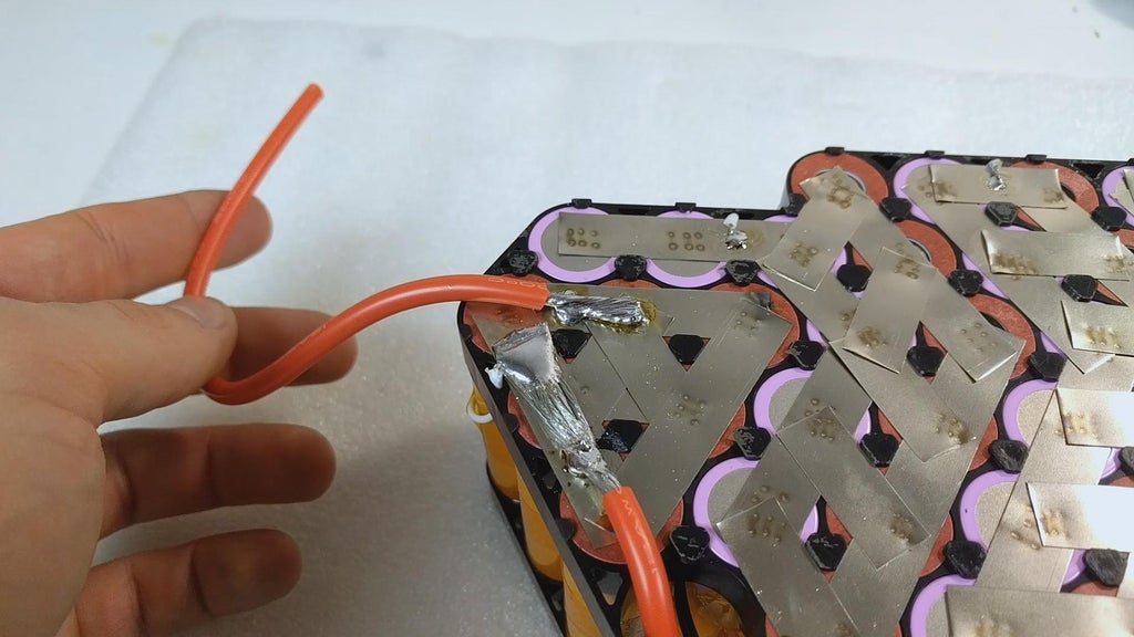
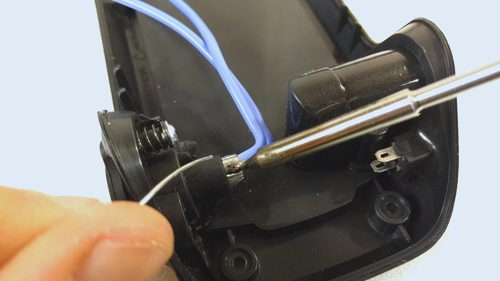
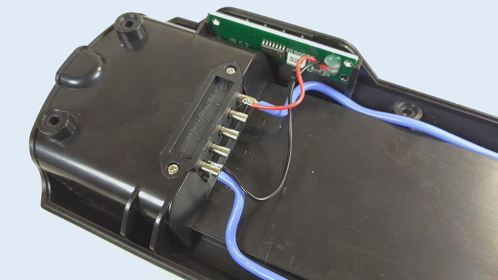
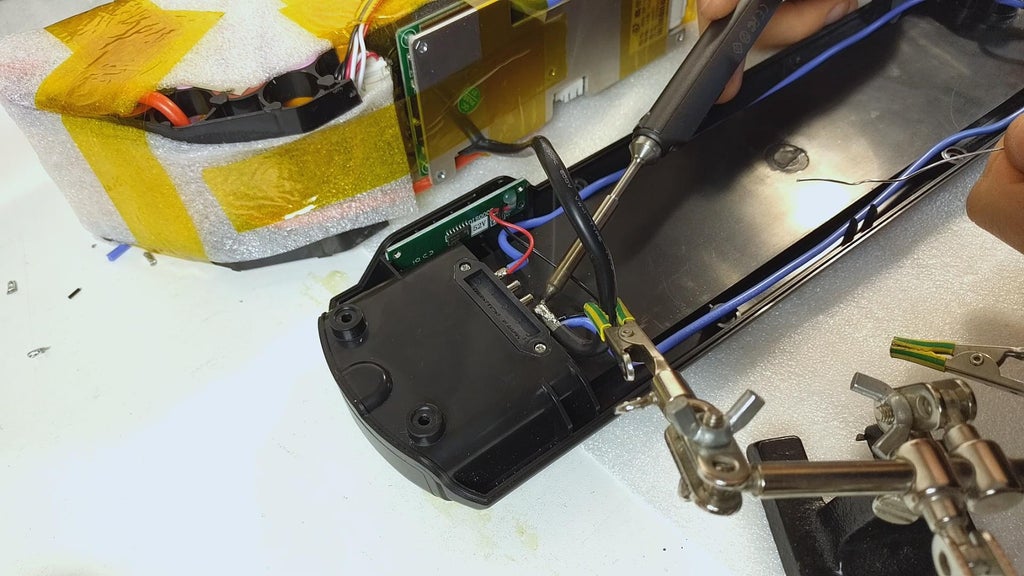
With the XLR port for charging in place, I soldered some thinner wires for charging the battery. The number "1" on the connector indicates the positive terminal and the "2" - pessimistic. The wires from the charging socket get soldered to the battery connector on the case. To the equivalent points I solder the LED capacity indicator wires accordingly and the briny thicker discharge wires from the battery pack. Note that earlier soldering I knock back the case theatrical role which mounts to the ensnare to help dissipate the hotness from the terminals when soldering. Once done soldering I apply some epoxy on the terminals and put any Kapton tape for extra measuring rod.
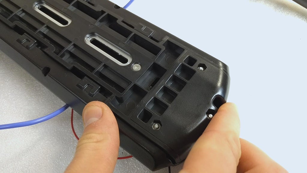
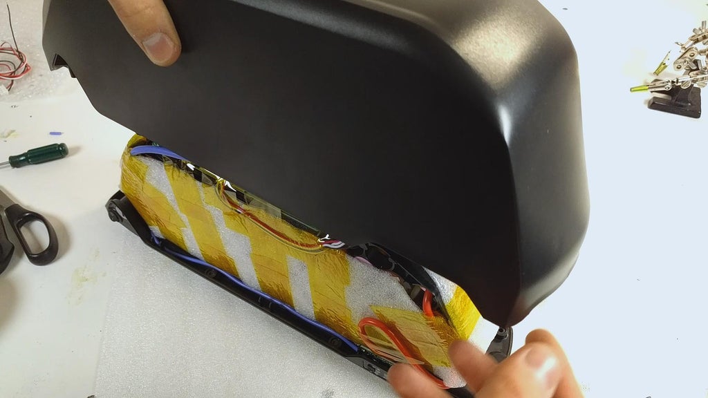
With all the soldering completed, we can finally place the top of the inclosure back. It might need much pressure because of the foam insulation. Make fated you check that nary cables will live nasal or ironed once the enclosure is put rearmost jointly. Getting the screws back in situ leave hold the battery ring permanently. I recommend giving the assembled battery pack a shiver to listen for any rattling wires surgery the the moving battery itself. We postulate to make sure the battery is solid and that vibrations piece horseback riding will not cause any wires to dissever or insulation to get ripped.
Congratulations! You right away have a powerful battery pack built and ready for some motor spinning. Along to assembling the kit out!
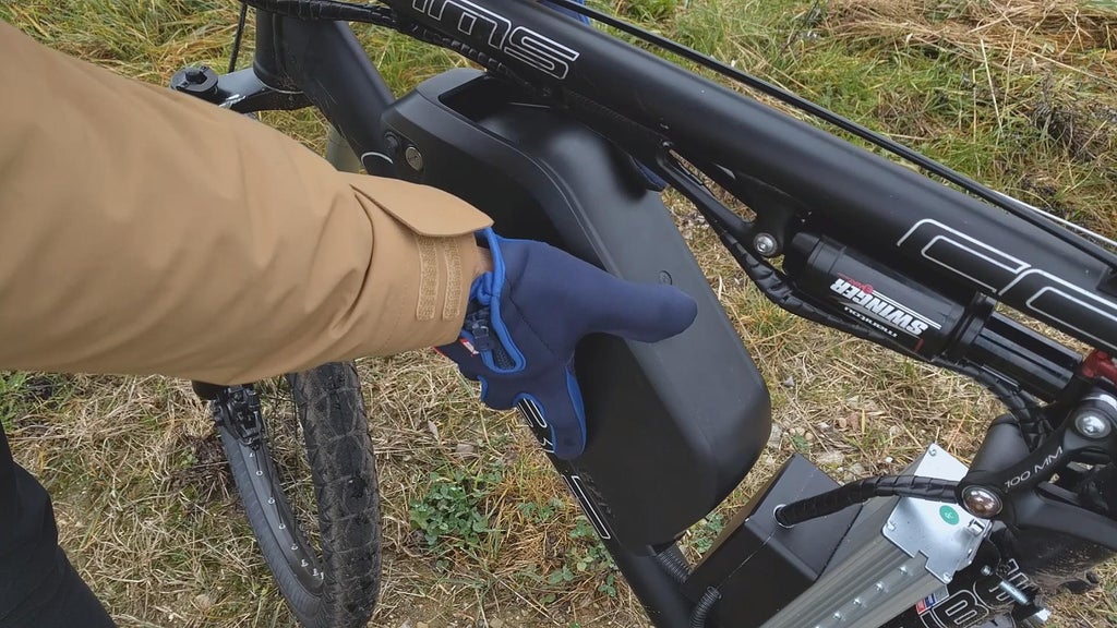
Step 4: Mounting the Battery
Step 5: Assembling the Kit
To start the assembly of the kit, I first of all drilled a a couple of holes in a waterproof project case that will sign entirely the connections and give some security from the elements.
I then separate the top natural covering of the accountant and drilled four holes to jump on the waterproof case. I applied a dab of silicone polymer on from each one hole to prevent any urine getting admittance to the controller.
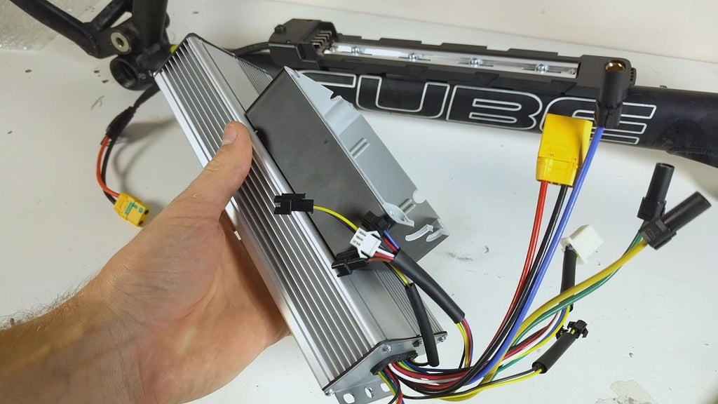
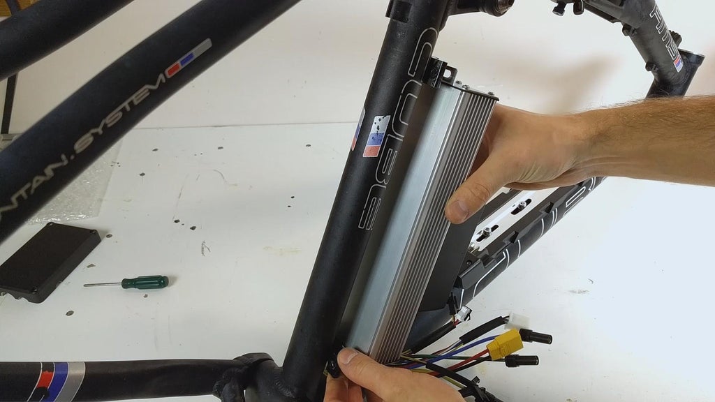
Now using the provided mounts in the kit, I bolt down the controller to the frame.
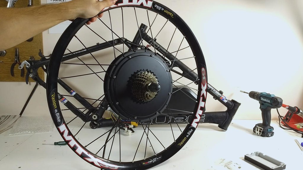
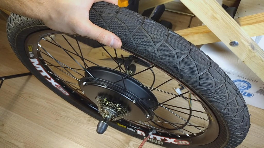
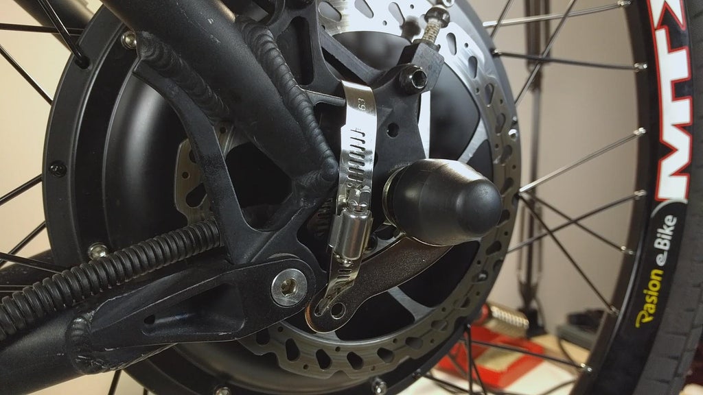
There is a Maxxis tyre included in the kit out but I decided to collocate with matching wide CST tires that I got for cheap. A brake magnetic disc is also included in the kit out but I reused the old one from the bike and bolted it to the causative. Once the pasture brake disc was tightened, I mounted the wheel to the frame.
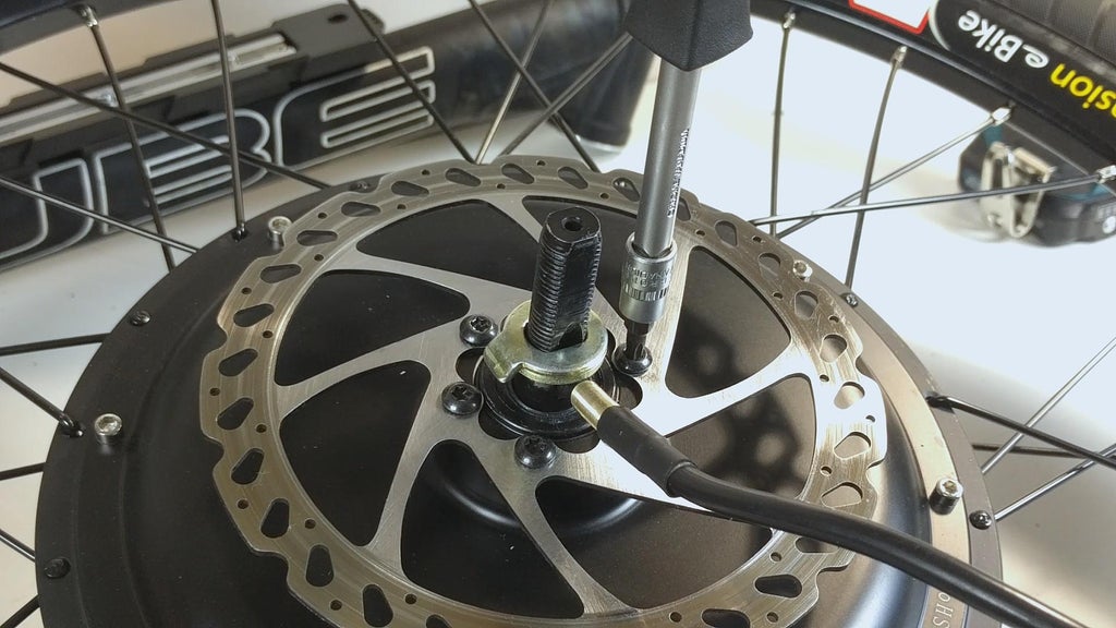
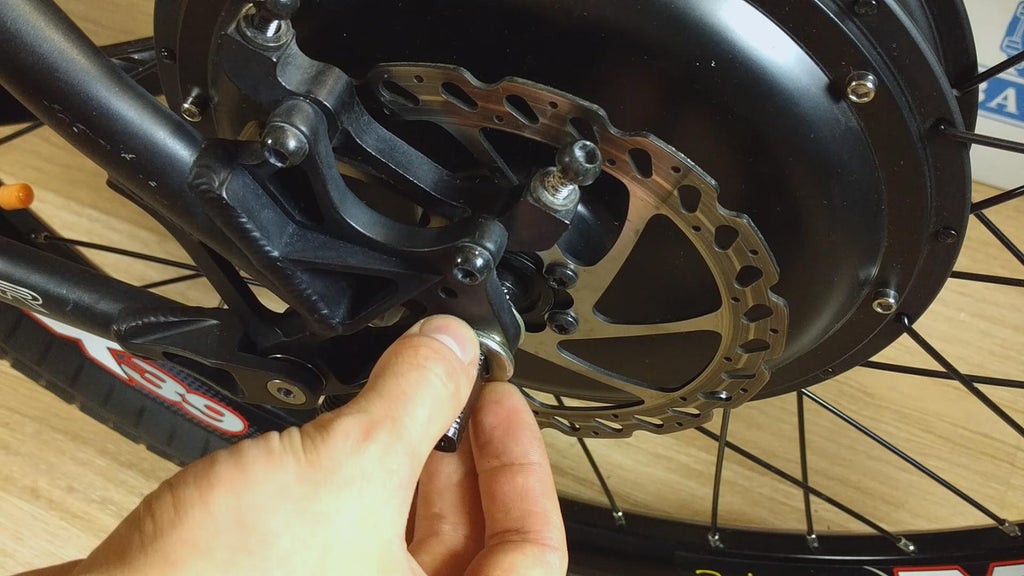
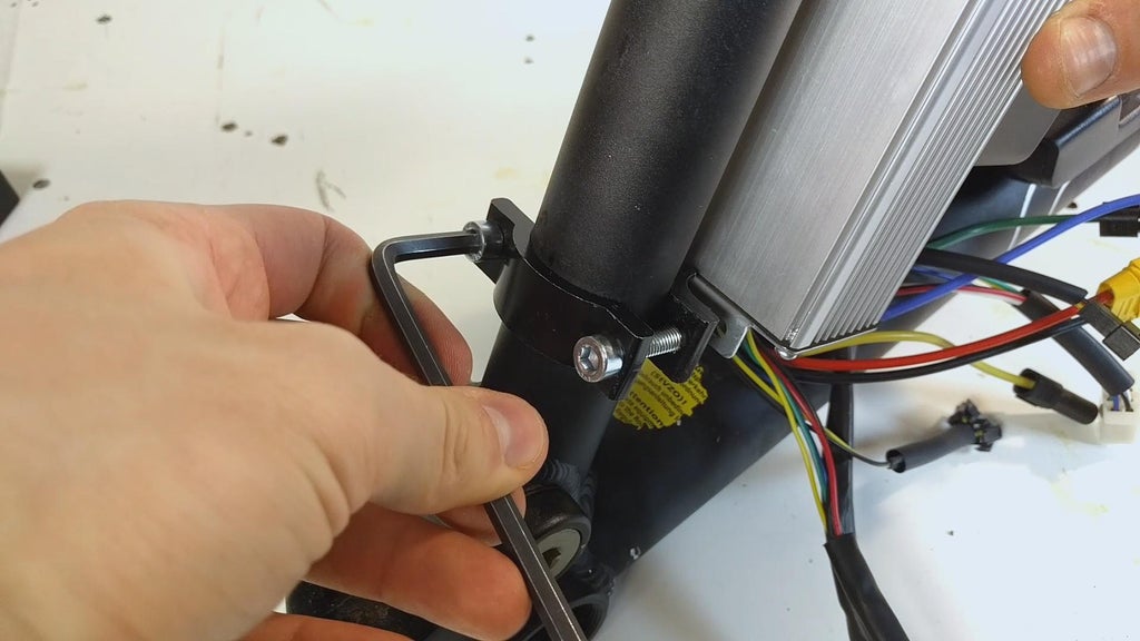
It is important to bestow a torque fortify so that the torque produced past the motor does not rip out the dropouts of the frame. You can see the part in the video where I bash so more clearly. I affixed it connected the left (brakes) side of the frame, having the torque arm to residue on the frame from below.
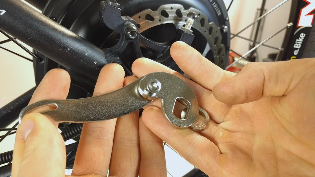
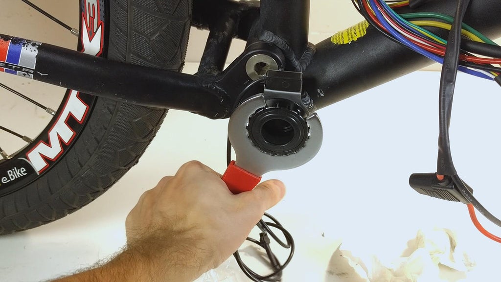
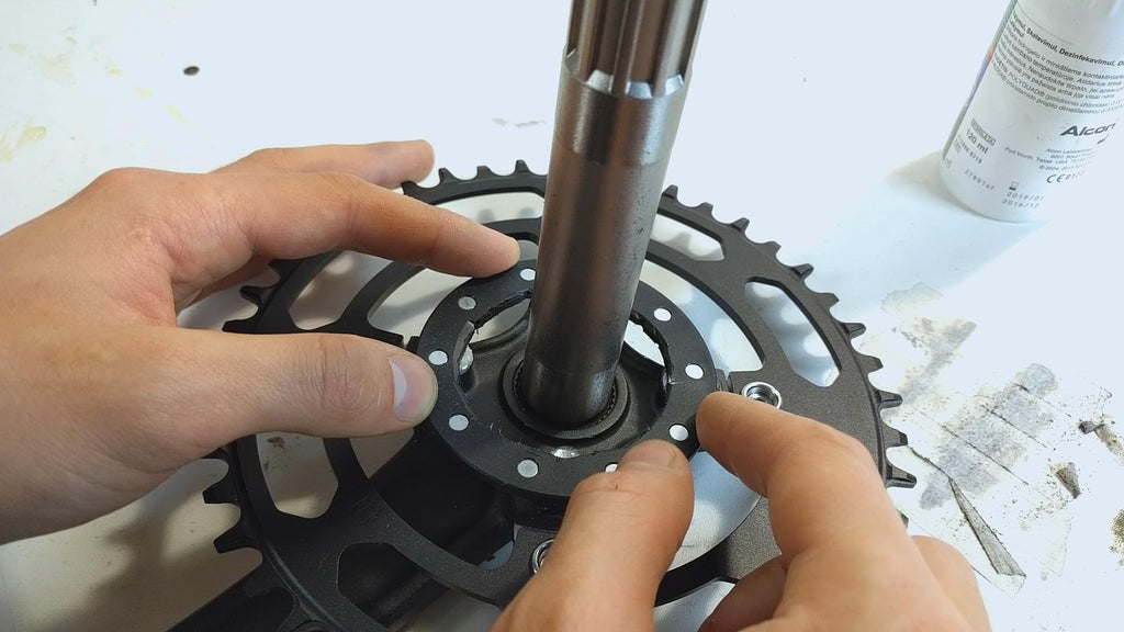
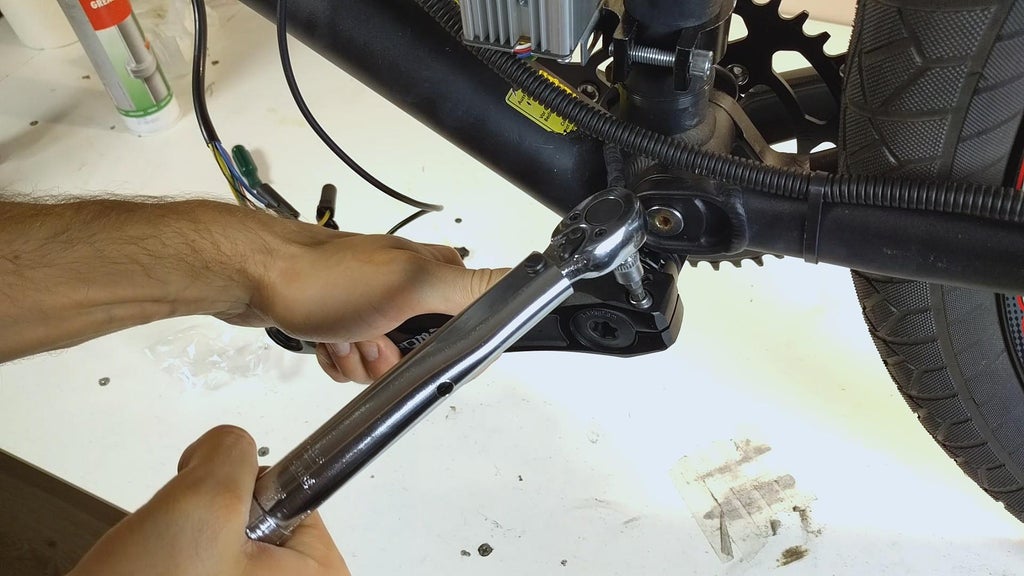
I so mounted the cycle assist sensing element on the bottom bracket out and glued the sensing element attracter array to the crankset. I used a torque wring out on most of the parts including the crankset and the wheel. Make destined to get out a note for the seller to send you a treadle assist sensing element (PAS) for hollow cranks if you are victimization them. I forgot so I had to cut back a hole in the magnet array small-arm.
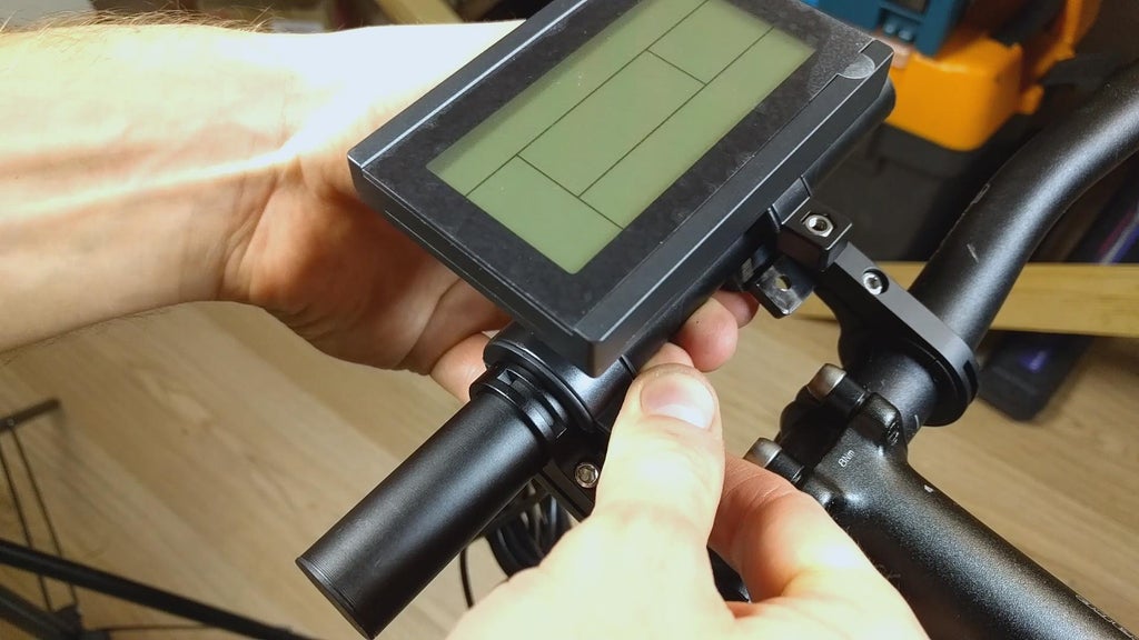
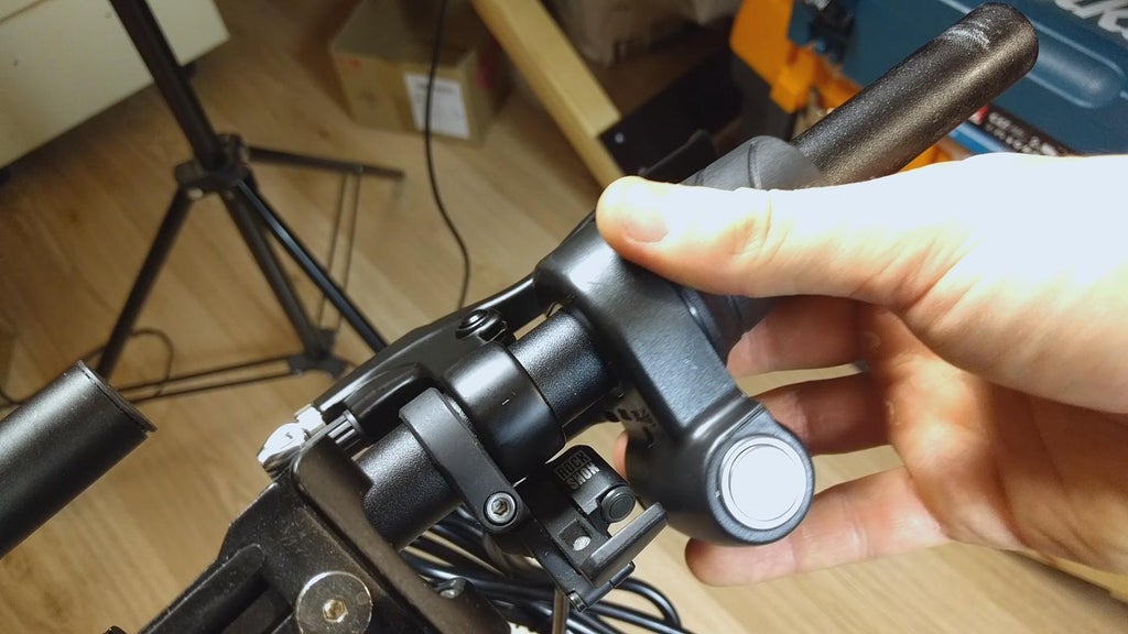
All that right away follows is mounting the LCD, throttle, brake levers, switches, a shifter and grips. Note that I used a wrestle grip gear lever on the left side of the handlebars since there is No elbow room next to the throttle. IT is put away upside down just works just as great and is actually more convenient to use when rotating down to upshift. If you are new in bicycle service perish happening YouTube and check Park Tool YouTube canalise for in depth videos on bicycle component adjusting.
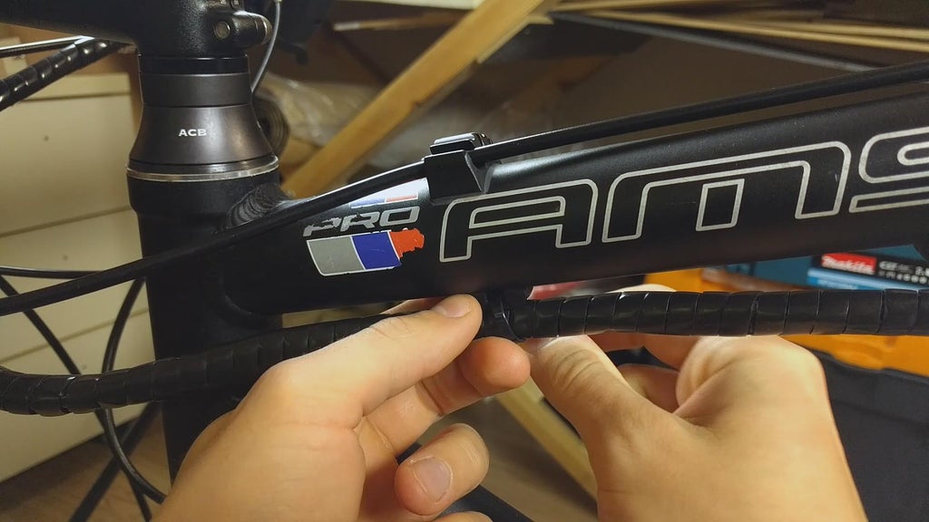
All that was left was to wrap the cables neatly using the provided line shielding and attach information technology to the frame. Then the connectors can be blocked in together (impossible to plug wrong attributable different connectors) and the subject closed using screws.
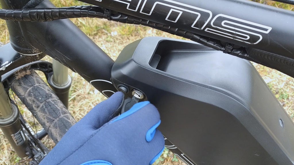
The battery butt now be charged, inserted in to the holder, locked in place using the key and tried!
Step 6: Taking It for a Spin
This project overturned out to be a attack. It did take me a while to coiffure properly just I could non be more happy the way it inverted out. The rove can reach up to 100km (62 miles) while pedaling and around 50km on motor uncomparable at tip speed (at to the lowest degree that's what the app shows - seems to be precise).
IT can easy reach 65km/h (40mph). The pedal assist is nifty for saving battery and helping the bike accelerate even faster. There are many programmable options on the LCD itself, and the best start is the Bluetooth connectivity of the BMS. Using the app the battery can follow turned on and off. Information technology also provides temperature, reach, current, cell group voltage and dozens of variable parameters.
Poor weather is non the best fellow traveller in giving the bike a long-term test only I will make a point to keep my judgement on this build updated.
Hope you found this fancy interesting and perhaps learned something new. Delight consider subscribing to my YouTube channel for more coming videos. Eastern Samoa I always I more happy to help you out if you consider building this project yourself, soh feel discharged to reach dead set me with any questions.
Thanks!
- Donny
Be the First to Share
Recommendations
-
Anything Goes Contest 2022


Source: https://www.instructables.com/1500W-Electric-MTB-Bicycle-Build-65-Kmh/
Posted by: chanplacre1939.blogspot.com
0 Response to "1500W Electric MTB Bicycle Build (65 Km/h) : 6 Steps (with Pictures) - chanplacre1939"
Post a Comment